
A tesla coil usually has these key components: *power source *Switching circuit *Resonant Capacitor (only for drsstcs, some vttc,s and regular spark gap type coils) *Primary coil *Secondary coil The tesla coil was invented around 1891 by Nikola Tesla. His original intention for the device was to create a wireless energy distribution system. Building a musical solid state Tesla Coil. 2 Pin output for Gate Drive Transformer (more on this later). This is easily done by using one 555 timer in Astable mode (which produces a continuous. A bit of salt was added to the breakout point which lends a yellow colouration to the sparks as the sodium ionizes and glows.
Here is a list of high voltage power supplies with schematics and construction details, going from simple to complex. Be careful if building any of these, high voltage can be dangerous! Simple flyback driver 10-15kV Probably the very first high voltage device built by any enthusiast. It uses a power transistor (2n3055) and two coils: a primary and a feedback on a flyback ferrite core. Schematics and details: 2. Push Pull (dual) 2n3055 flyback driver You can use 2 x 2n3055 transistors in a better circuit that provides more power.
However this too is prone to failure due to the transistor limitations. A large heatsink is required as well. Voltage multipliers If the flyback doesn’t provide the voltage you require, a solution is to build a voltage multiplier. You can hook it to any flyback secondaries that doesn’t have built-in rectification (diodes or multipliers). A very easy to build design is the Villard cascade voltage multiplier: To understand how it works, you can read more on it.
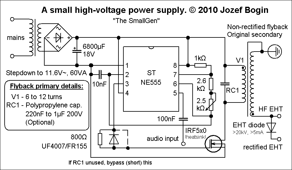
I’ve built mine in a plastic CD box, this way I can add liquid wax for better insulation. Here are some interesting tests using the multiplier: 4. 555 Timer flyback driver This circuit uses a 555 timer IC to pulse a power transistor with square wave at a frequency that is set by the capacitor and the potentiometers.
It is a very efficient circuit, assuming the frequency is correctly adjusted. Circuit diagram: See it in action. 555 Timer dual ignition coil 30KV An even better approach for those that seek more power and higher voltages is using ignition coils from cars. I’ve got 2 from a scrapyard, and connected them in anti parallel: The driver used is the same as above (with a 555 timer), the difference is in using a different pot, resistors and capacitor for another frequency interval, and stronger mosfet, suitable for ignition coils: Adjusting the frequency with the pot, I got some tick white arcs, similar to those produced by a flyback with a ZVS driver.
A good indication of the power running in the system. ZVS Flyback driver A powerful driver with excellent results (no transistor heating, a lot of power pushed), is the ZVS (push/pull) driver, that was described in. Here is the circuit diagram: 6. Dual Flyback driver ZVS gives a lot of power, but the voltage is not great. You might want to put two flybacks in series, and use 2 separate ZVS drivers, or a single driver with the 5+5 primary coil wrapped around both ferrite cores: 7.
Tesla Coil The ultimate in high voltage records, this device was discussed. Taking advantage of the way the secondary is constructed, several issues are solved by construction: the secondary insulation is trivial. High frequency Solid state tesla coil (HFSSTC): More on the HFSSTC. To be continued.
Sertifikat sootvetstviya na krani sharovie bologoe. Sep 29, 2013 Sertifikat za somborski sir Radio Televizija Vojvodine. This feature is not available right now. Somborski sir iz kačice dobio je nacionalni sertifikat o geografskom poreklu. Items Ramki s ikonitie na 'Isusa Khrista' i 'sv. Bogoroditsa,' i tsarski vrata v postnitsata na 'sv. Luka' v Rilskiia m'nastir.
Folosesc bobine de inductie (sunt detapt transformatoare nu autotrafo) de la Chevrolet Cavalier(sunt in philly, sua) legate in paralel la intrare si in serie la iesire. Folosesc mnosfeturi sau igbt-uri de putere ca switch, dar tot mi se prajesc pentru ca e prea mare tensiune autoindusa din primar. Trebuie sa fac un snubber mai bunFusorul (am sa fac niste pozeodata) n-a functionat niciodata cu deuteriu sau altceva decat cu aer,e bun numai de bronzat la fata ca in felul acesta (grila externa, grila interna) n-o sa scoata energie extra niciodata!
Tyc, use a totem pole setup (generic PNP+NPN) before the mosfet, just to be on the safe side. I’m not familiar with the 7555, but regular 555 will NOT work with a mosfet. So just add the totem pole and see if this helps. You say you’re using an induction coil? Please note that an induction coil works at much Lower frequencies than a Flyback transformer. Instead of the 100nF capacitor, try as high as 1uF. When the coil works best, you should hear an annoying bass-like sound, like a strong vibration coming out of the coil, and NOT that high-frequency sound like in the case of ferrite core transformers.
Last issue, indeed the coil might be broken, you should be able to measure the resistance of the secondary, if it’s >4KO the coil should be ok, but this is not the best test. Note that there is an even easier circuit you can try, using a Light Dimmer and a capacitor like shown here: However I never tried that setup yet.